
Desert Online General Trading LLC
Dubai, United Arab Emirates
Desert Online General Trading LLC
Dubai, United Arab Emirates
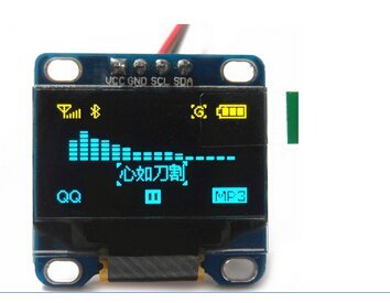
Interface: IIC/I2CVCC: 2.2V-5.5VGND: Power GoundSCL: CLK clock (High level 2.2V-5.5V)SDA: MOSI data (High level 2.2V-5.5V)Feature:Color: Blue and YellowResolution: 128x64Power: 0.06WWide power supply range: DC 3V-5VTemperature: -30°C to 70°CDimension: 29.28 x 27.1 mm (LW)Compatible with 3.3V and 5V control chip I / O levelOLED internal drive chip: SSD1306Package included:1 x Blue and Yellow SPI OLED display
J**D
Seems ok, though --> NOTE POLARITY OF POWER PINS <--
So - this is basically a clone of the Heltec/DIYmall SSD1306 displays which I've used a bunch. Build quality isn't QUITE as up there - you'll probably want to throw some hot-melt under the lower two corners of the screen to give the thin glass a little support. I've had other screens from other sellers break in that spot during shipping, and there are conductors through there - so if it breaks, display is dead.I was getting geared up to write a scathingly bad review, as I popped this thing into a prototype that worked with one of the other OLED's and the board wouldn't boot, and it was trying to draw over 700ma from a device which normally draws 50.But then, you'll note that the positions of the VCC and GND pins are reversed from the positions of literally every other i2c OLED with this form factor that I've used. OH. Quick surgery of the prototype and the display works on I2C addy 0x3C.Tested for over an hour, no issues as yet.
O**N
Works! Here are the pinouts for the SPI version.
The driver IC on here is an SSD1306. To confirm which version of the display you have, look at the back of the display. Notice the little table printed on there. Compare that with R1-R4 to the right. If you see resistors in all positions listed for a particular interface, that is the one that will be in use.Here are the pinouts for the SPI version which aren't quite right as listed in the vendor description:GND: Power GroundVCC: 2.2V-5.5VSCL: SCLK (SPI clock)SDA: MOSI (SPI data)RST: Reset Pin for SSD1306D/C: Data/Command Pin for SSD1306Notice that the only SPI pins on the header are SCLK and MOSI. There is no MISO (display never sends data) or CS (chip select)!The lack of a CS pin could be a problem if you need to have more than one device on the same SPI lines. While the SSD1306 does have a CS pin, the vendor didn't expose one to the headers for some reason. It is possible that one of the resistor pads on the back connects to CS because it is supposed to be always pulled low for I2C and needs to be pulled low for SPI to work, but I have no idea which one it is.RST is normally high and is set low for 3+ us to reset the state of the SSD1306.D/C tells the SSD1306 whether to interpret data coming over the MOSI line as a display command or bitmap data. High for data to be written to display ram, low for command.RST and D/C are outside the SPI spec so any GPIO pins can be used for these functions.To get this working on a Raspberry PI, clone the git repo the-raspberry-pi-guy/OLED - the sample code there uses GPIO#14 for RST and GPIO#15 for D/C.
S**R
Bright display--works well.
Worked well with the Adafruit GFX library. Only wrinkle is that the I2C address is 0x3C, NOT 0x78 as printed on the back of the display. Also note that Vcc is +5VDC (this is not listed in the product description).
S**H
Became extremely dim after a day
This thing worked for all of a day, then suddenly became so dim it's unreadable. I've tried it on several different micro controllers with the same results. Worried that despite the sellers claims of it being usable with 5v that it actually isn't. I've tried everything I know how to do in software to get it going back to the way it was but nothing is working.You can see the pics. One shows it working great. I was please. Now (and at the time of this writing) it completely went out. Shame.
Trustpilot
2 weeks ago
5 days ago
1 day ago
2 weeks ago